- Get link
- X
- Other Apps

It was a little over a year ago, that I broke the news that Microsoft had stopped the development of HoloLens V2 and was pushing forward to V3. Since then, I have been asked about a million times for more information about the upcoming device but if you know where to look, the company is developing the hardware in broad daylight.
Based on documents I was able to view, Microsoft is still targeting a Q1 release of the next gen headset. Additionally, the company is referring to the project internally as Sydney.
The device, according to the documents, will be lighter, more comfortable to wear, and have significantly improved holographic displays. But most importantly, it will cost significantly less than the current version of the HoloLens.
All of this is the natural evolution for the second generation of a piece of hardware but the good news is that it’s still on track for a release early next year.
What I don’t know is if the Q1 date is for general availability or for a developer preview. I could see Microsoft seeding the newer higher-end devices to developers prior to the general release of the hardware but that is only speculation at this time.
Based on the documents I was able to view, Microsoft is approaching the MR/VR market as a must-win market. This is likely because they are on the sidelines of the smartphone segment and missing out on this generation of devices would inflict serious long-term ramifications for the company about being anything more than a cloud company.
For Microsoft, they currently have an advantage in this space as they are shipping hardware but Apple, Google, Magic Leap, and many others are investing in this space heavily which means they won’t be the only competitor in this segment for long.
New patent promises to double Field of View of HoloLens v2
Besides the cost, the biggest issue with the Microsoft HoloLens is the Field of View (FoV) which at 35 degrees has been described as looking at the world through a mail slot.
Microsoft has not made it a secret that they are working on HoloLens v2, and has been explicit about the improved Holographic Processing Unit and improved Kinect-based Depth Sensing Unit.
What Microsoft has not talked about much however has been the optics of the device, but now a new patent suggests Microsoft may have achieved the breakthrough they have been after.
Titled “MEMS LASER SCANNER HAVING ENLARGED FOV”, the December 2016 patent applications explains the method below:
A MEMS laser scanner is disclosed for use in a near-eye display including an increased field of view (FOV). In embodiments, one or more polarization gratings may be applied to the mirror of the MEMS laser scanner, which polarization gratings may be configured according to the Bragg regime. Using light of different polarizations, the MEMS laser scanner is able to expand the FOV without increasing the range over which the mirror of the scanner oscillates.
The process is illustrated as below:
MS patent "MEMS LASER SCANNER HAVING ENLARGED FOV" https://t.co/PZLatNZkNB also it mentions MicroVision PicoP pic.twitter.com/SJ1RjQvbn5— WalkingCat (@h0x0d) June 25, 2018
MEMS LASER SCANNER HAVING ENLARGED FOV
[excerpted]
Abstract: A MEMS laser scanner is disclosed for use in a near-eye display including an increased field of view (FOV). In embodiments, one or more polarization gratings may be applied to the mirror of the MEMS laser scanner, which polarization gratings may be configured according to the Bragg regime. Using light of different polarizations, the MEMS laser scanner is able to expand the FOV without increasing the range over which the mirror of the scanner oscillates.
Assignee:
Microsoft Technology Licensing, LLC (Redmond, WA, US)
Publication Date:
06/21/2018
Filing Date:
12/16/2016
View Patent Images:
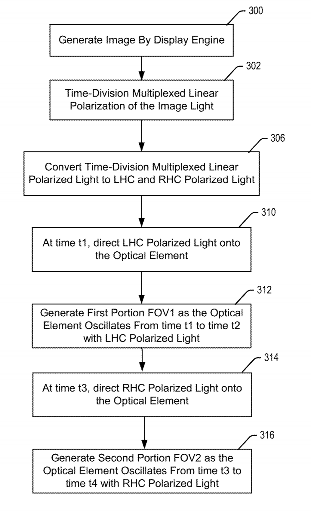
The image light is generated by a display engine 140 which emits image light in a step 300 that is modulated on a pixel-by-pixel basis by the controller 124. In embodiments, the display engine 140 may be a commercially available assembly, such as for example the PicoP™ display engine from Microvision, Inc. of Redmond, Wash.
BACKGROUND
Various types of computing, entertainment, and/or mobile devices can be implemented with a near-eye transparent or semi-transparent display. Near-eye displays may include a transparent or semi-transparent display through which a user may view the surrounding environment, and also see images of virtual objects (e.g., text, graphics, video, etc.) that are generated on the display to appear as a part of, and/or overlaid upon, the surrounding environment.
Near-eye displays have conventionally been implemented using spatial light modulation (SLM) systems including for example liquid crystal on silicon (LCoS) display engines and digital light processing (DLP) display engines for generating an image. LCoS and DLP display systems project all pixels in an image simultaneously, modulating the amplitude, phase, intensity or polarization of light across the image. Another emerging technology is microelectromechanical (MEMS) laser scanners. MEMS laser scanners conventionally include a laser light source including for example red, green and blue laser diodes directing RGB laser light to a MEMS mirror capable of deflection about two orthogonal axes.
In contrast to LCoS and DLP displays, MEMS laser scanners typically generate a two-dimensional raster scan image pixel by pixel for each image frame. The laser light source is synchronized with the bi-axial MEMS mirror drivers so that bi-axial deflection of the MEMS mirror directs laser light from the light source to the respective pixels in the raster scan, as the RGB laser light for each pixel is modulated to thus generate the desired light content of each pixel in the image.
The bi-axial range of motion of the MEMS mirror in a near-eye display laser scanner establishes the size of the field of view (FOV) that the laser scanner can generate. However, various factors impede the pivoting range of motion of a MEMS mirror during the scanning of an image frame. These factors include for example the mass of the MEMS mirror, as well as the opposing forces of air (or other gas) against the mirror surface as it pivots. Currently, MEMS mirrors in near-eye display laser scanners commonly achieve a range of motion of about 30 degrees, and an FOV of about 35 degrees.
SUMMARY
Certain embodiments of the present technology relate to a MEMS laser scanner for use in a near-eye display including an increased field of view (FOV). In embodiments, one or more polarization gratings may be applied to the mirror of the MEMS laser scanner, which polarization gratings may be configured according to the Bragg regime.
The one or more polarization gratings diffract polarized light from a laser image source in two different directions, depending on the polarization of the light, according to a time-division multiplexed scheme. The MEMS scanner pivots back and forth through its range of motion about an axis to complete one full stroke. During the time that the MEMS scanner pivots about an axis through a first half of its stroke, the laser image light may be polarized for example as LHC polarized light. The one or more polarization gratings may be tuned to allow a zero order of the LHC polarized light to pass straight through the grating un-diffracted and reflect off the MEMS mirror at an angle equal to the angle of incidence. As the MEMS scanner pivots through its first half stroke, the un-diffracted zero order light traces out a first portion of the FOV.
During the time that the MEMS scanner pivots about the axis through a second half of its stroke, the laser light may be polarized for example as RHC polarized light. The one or more polarization gratings may be tuned to diffract a first order of the RHC polarized light in reflection off the MEMS scanner at some angle greater than the mirror angle. As the MEMS scanner pivots through its range of motion, the diffracted first order light traces out a second portion of the FOV. The first and second portions of the FOV may overlap and combine to provide an enlarged overall FOV.
Comments
Post a Comment